SMAJ15A - 15V Unidirectional TVS Diode
High-performance Transient Voltage Suppressor (TVS) diode for overvoltage protection on +12V and -12V power rails.

Overview
The SMAJ15A is a unidirectional TVS diode that provides fast-response overvoltage protection for sensitive electronics. In this power supply design, it protects the +12V and -12V output rails from voltage transients and ESD events.
Part Information
| Parameter | Value |
|---|---|
| JLCPCB Part Number | C571368 |
| Manufacturer Part Number | SMAJ15A |
| Package | SMA (DO-214AC) |
| Stock | 713 units |
| Estimated Price | $0.15 |
| Direction | Unidirectional (one-way protection) |
Electrical Specifications
Voltage Characteristics
| Parameter | Symbol | Min | Typ | Max | Unit |
|---|---|---|---|---|---|
| Standoff Voltage | V_RWM | - | 15 | - | V |
| Breakdown Voltage | V_BR | 16.7 | - | 18.5 | V |
| Clamping Voltage @ 16.4A | V_C | - | - | 24.4 | V |
| Reverse Leakage Current | I_R | - | - | 5 | µA |
Power and Current Ratings
| Parameter | Symbol | Value | Unit | Conditions |
|---|---|---|---|---|
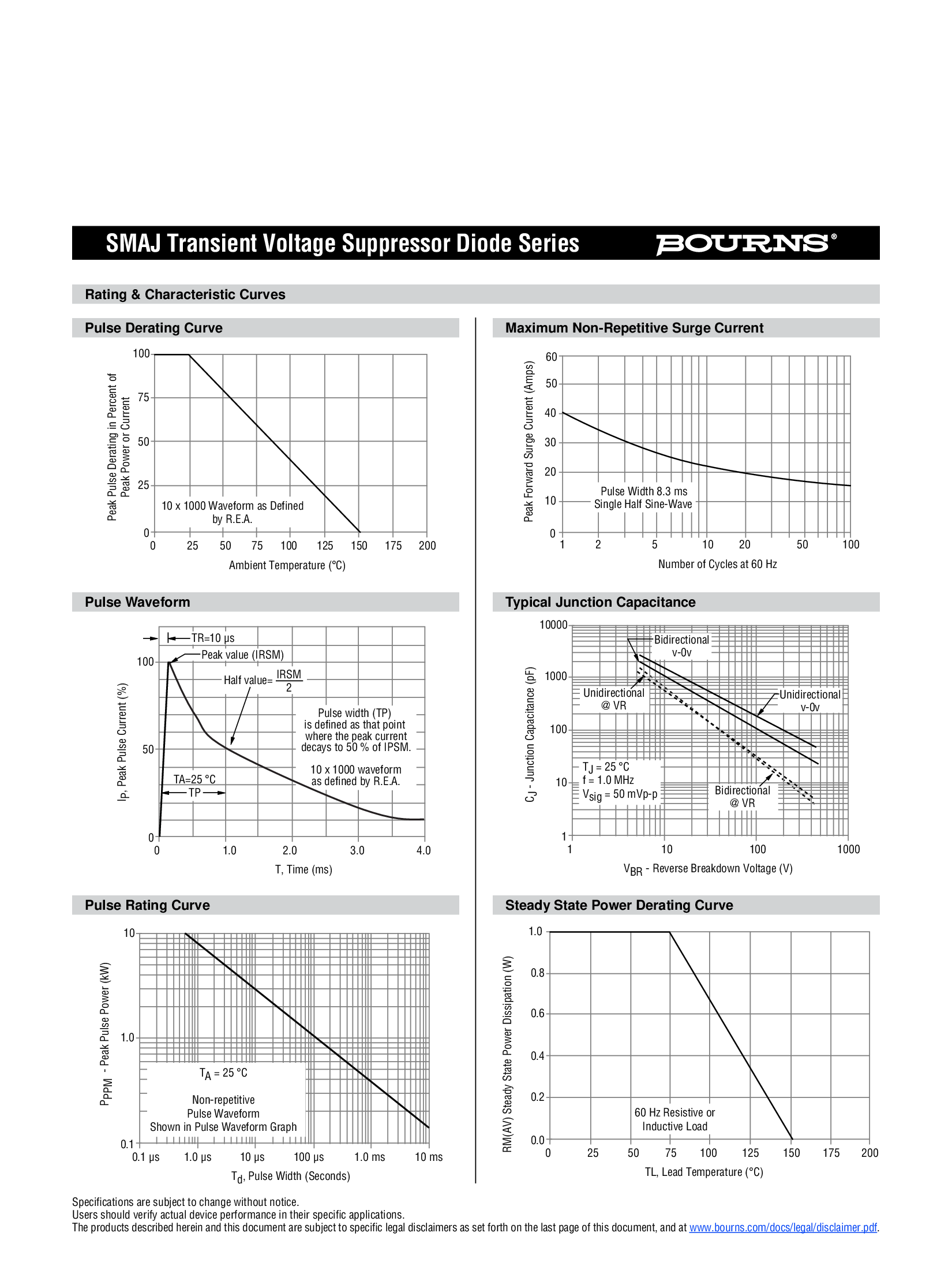
| Peak Pulse Power | P_PPM | 400 | W | 10/1000µs waveform |
| Peak Pulse Current | I_PPM | 16.4 | A | 10/1000µs waveform |
| Maximum Reverse Voltage | V_RWM | 15 | V | Continuous operation |
| Maximum Clamping Voltage | V_C | 24.4 | V | @ I_PP = 16.4A |
Dynamic Characteristics
| Parameter | Value | Unit |
|---|---|---|
| Response Time | <1 | ns to picoseconds |
| Junction Capacitance | ~500 | pF @ 0V |
| Operating Temperature | -55 to +150 | °C |
| Storage Temperature | -65 to +175 | °C |
How TVS Diodes Work
Normal Operation
During normal operation (voltage below standoff voltage):
Normal State (V < 15V):
+12V Rail ─────┬─────→ To Load
│
[TVS1] Cathode (marked end)
│
GND (Reverse leakage: <5µA)The TVS diode acts as an open circuit with only minimal leakage current (<5µA).
Transient Protection
When a voltage spike occurs:
Transient Event (V > 16.7V):
    +12V Rail ─────┬─────→ Protected Load
                   │         (Voltage clamped to 24.4V max)
                 [TVS1] ⚡ CONDUCTING
                   │
GND (Shunting transient energy to ground)Detection: Voltage exceeds breakdown voltage (16.7V)
Response: TVS conducts in <1ns
Clamping: Voltage limited to 24.4V maximum
Energy Dissipation: Transient energy safely dissipated to ground
Recovery: Returns to high-impedance state when voltage normalizes
Circuit Placement
TVS1: +12V Rail Protection
Linear Regulator Output:
    U6 (L7812CV-DG)
        │
        ├─→ C17 (470µF) ─→ GND
        │
        ├─→ C14 (100nF) ─→ GND
        │
        ├─→ [TVS1] SMAJ15A ─→ GND
        │      ↑
        │   Cathode to +12V
        │   Anode to GND
        │
        ├─→ PTC1 (1.1A) ─→ LED2 (Green) ─→ +12V OUTPUT
TVS3: -12V Rail Protection
Negative Rail Protection:
    U8 (CJ7912)
        │
        ├─→ C21 (470µF) ─→ GND
        │
        ├─→ C16 (100nF) ─→ GND
        │
        ├─→ [TVS3] SMAJ15A (reversed)
        │      ↑
        │   Cathode to GND
        │   Anode to -12V
        │
        ├─→ PTC3 (1.1A) ─→ LED4 (Red) ─→ -12V OUTPUT

Special Note: For negative rail protection, TVS3 is reversed:
- Cathode connects to GROUND
- Anode connects to -12V rail
This protects against negative voltage spikes below -16.7V
Pin Configuration
SMA Package (DO-214AC)
    ┌─────────────┐
    │             │  Cathode (marked end with band)
    │   SMAJ15A   │  Connect to protected +rail
    │             │
    └─────────────┘  Anode (unmarked end)
                     Connect to ground
Polarity Identification
Cathode: End with marking band (white or colored stripe)
Anode: Unmarked end
Connection Rules
| Application | Cathode | Anode |
|---|---|---|
| +12V Rail (TVS1) | Connect to +12V | Connect to GND |
| -12V Rail (TVS3) | Connect to GND | Connect to -12V |
Application Notes
1. Unidirectional vs Bidirectional
Unidirectional (SMAJ15A):
Protects against voltage spikes in ONE direction only
Used for DC power rails with known polarity
Lower capacitance than bidirectional types
TVS1: Protects +12V from positive spikes above +16.7V
TVS3: Protects -12V from negative spikes below -16.7V (when reversed)
Note: For the +5V rail in this project, we use the SD05 unidirectional TVS diode, which is optimized for DC power rail protection.
2. Clamping Voltage Selection
The SMAJ15A is chosen for 12V rails because:
| Rail Voltage | TVS Standoff | TVS Breakdown | Max Clamp | Safety Margin |
|---|---|---|---|---|
| +12V nominal | 15V | 16.7V | 24.4V | 4.7V above nominal |
| -12V nominal | 15V | 16.7V | 24.4V | 4.7V above nominal |
Design Criteria:
Standoff voltage (15V) > Normal operating voltage (12V) ✓
Breakdown voltage (16.7V) protects against transients ✓
Clamping voltage (24.4V) below component damage threshold ✓
Adequate margin for voltage regulation tolerance ✓
3. Peak Pulse Power Rating
The 400W rating is specified for a 10/1000µs waveform:
Voltage Pulse Profile:This waveform simulates:
Lightning-induced surges
Inductive switching transients
Power line disturbances
4. Response Time Characteristics
Transient Response Timeline:
    Spike        TVS           Voltage
    Detected     Conducts      Clamped
       ↓            ↓             ↓
    ───┴────────────┴─────────────┴────→ Time
       0          <1ns         stable
                 (subnanosecond response)
The <1ns response time means the TVS diode begins conducting almost instantaneously, protecting downstream circuitry before the transient can cause damage.
5. Placement Guidelines
Optimal Placement:
✓ GOOD: Close to load
    Regulator → [Cap] → [TVS] → Load
                  ↓       ↓
                 GND     GND
    (Short traces minimize inductance)

✗ POOR: Far from load
    Regulator → [Cap] → ─────── (long trace) ─────── → Load
                  ↓                                      ↓
                 GND                                    [TVS]
                                                         ↓
                                                        GND
    (Trace inductance can allow voltage spikes)
Best Practices:
Place TVS diode as close to protected load as possible
Use short, wide traces to minimize parasitic inductance
Connect anode directly to ground plane
Keep ground return path short and low-impedance
Place after fuses and PTCs in protection chain
6. Thermal Considerations
Power Dissipation:
Normal operation: ~75µW (15V × 5µA leakage)
Transient events: Up to 400W for 10/1000µs pulses
Repetitive pulse rating: Consult derating curves in datasheet
No heat sink required for this application because:
Continuous power dissipation is negligible
Transient events are brief and infrequent
SMA package provides adequate thermal mass
7. Testing and Verification
Functional Test:
Measure standoff voltage: Should be >15V reverse breakdown
Verify leakage current: Should be <5µA at 15V
Optional: Use surge generator to verify clamping (requires specialized equipment)
Visual Inspection:
Verify correct polarity (cathode band orientation)
Check for proper soldering (no cold joints)
Ensure component is not cracked or damaged
ESD and Transient Protection Standards
Compliance
The SMAJ15A provides protection compliant with:
IEC 61000-4-2 (ESD immunity)
IEC 61000-4-4 (Electrical fast transient)
IEC 61000-4-5 (Surge immunity)
Protection Levels
| Standard | Test | Level | SMAJ15A Capability |
|---|---|---|---|
| IEC 61000-4-2 | ESD | ±8kV contact | ✓ Exceeds |
| IEC 61000-4-4 | EFT | 4kV | ✓ Exceeds |
| IEC 61000-4-5 | Surge | 1kV | ✓ Exceeds |
Comparison with Alternatives
SMAJ Series Comparison
| Part Number | Standoff | Breakdown | Clamp @ 16.4A | Application |
|---|---|---|---|---|
| SMAJ12A | 12V | 13.3V | 19.9V | Lower voltage rails |
| SMAJ15A | 15V | 16.7V | 24.4V | ±12V rails (this project) |
| SMAJ18A | 18V | 20.0V | 29.2V | Higher voltage rails |
| SMAJ24A | 24V | 26.7V | 38.9V | 24V systems |
When to Use Different TVS Ratings
Selection Guide:
    Working Voltage → Add 20% margin → Select TVS Standoff Voltage

Examples:
    5V rail   → 5V × 1.2 = 6V   → Use SMAJ5.0A or SMAJ6.0A
    12V rail  → 12V × 1.2 = 14.4V → Use SMAJ15A ✓
    15V rail  → 15V × 1.2 = 18V  → Use SMAJ18A
    24V rail  → 24V × 1.2 = 28.8V → Use SMAJ30A
Application in This Project
Usage Summary
| Component | Rail | Function | Quantity |
|---|---|---|---|
| TVS1 | +12V | Positive spike protection | 1 |
| TVS3 | -12V | Negative spike protection (reversed) | 1 |
Protection Chain
The SMAJ15A is part of a multi-stage protection system:
Complete Protection Architecture:
    Input → [Fuse] → [PTC] → [TVS] → Load
            ❶        ❷        ❸

❶ Fuse (F1): Short circuit protection (permanent, requires replacement)
❷ PTC: Overload protection (resettable, 30-second recovery)
❸ TVS: Transient voltage protection (automatic, sub-nanosecond response)
Protection Coordination
| Fault Condition | Response | Recovery |
|---|---|---|
| Voltage spike | TVS clamps | Automatic |
| Overload | PTC trips | 30 seconds |
| Short circuit | Fuse blows | Manual replacement |
Related Components
SD05 - 5V Unidirectional TVS Diode (for +5V rail)
Protection Circuit Overview - Coming soon
PCB Layout Guidelines - Coming soon
References
IEC 61000-4-x Standards Documentation
Last updated: 2025-12-28