USB Type-C Receptacle Connector
6-pin USB Type-C receptacle connector for USB Power Delivery (PD) input and power negotiation (power-only configuration).

Overview
The USB Type-C receptacle connector (J1) serves as the power input interface for this modular synthesizer power supply. It receives power from USB-C PD chargers and provides the necessary connections for the STUSB4500 USB-PD controller to negotiate 15V/3A power delivery.
This design uses a 6-pin power-only USB Type-C connector optimized for USB-PD applications where data transfer is not needed. The 6-pin configuration includes only the essential pins for power delivery: VBUS, GND, and CC (Configuration Channel) pins.
USB Type-C features a reversible connector design, allowing insertion in either orientation. The connector uses CC (Configuration Channel) pins to detect orientation and negotiate power delivery profiles with compatible chargers.
Key Specifications
| Parameter | Value | Notes |
|---|---|---|
| JLCPCB Part Number | C456012 | This design |
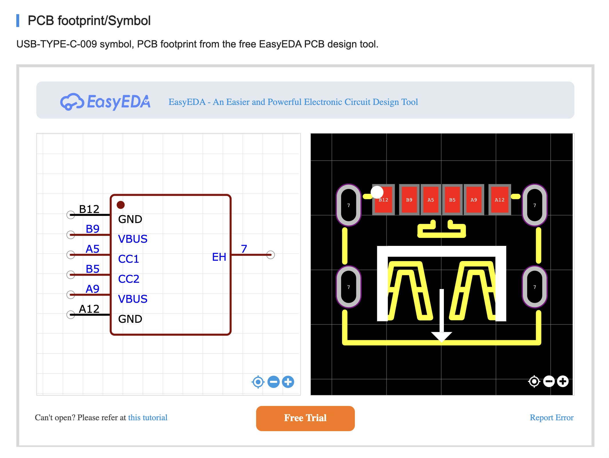
| Manufacturer Part Number | USB-TYPE-C-009 | |
| Package | SMD (Surface Mount) | 6-pin power-only |
| Stock Availability | 22,140 units | Good availability |
| Pin Count | 6 pins | Power-only configuration |
| Current Rating | 3A typical | Sufficient for USB-PD |
| Voltage Rating | 20V maximum | USB PD 3.0 compatible |
| Mounting Type | SMD (mid-mount) | |
| Durability | 10,000+ mating cycles | Typical |
Pin Configuration
The 6-pin USB Type-C connector provides only the essential pins for USB Power Delivery:
USB Type-C 6-Pin Connector (Power-Only)
Receptacle Front View (looking into the connector)

    ┌──────────────────┐
    │   1    2    3    │  Top Row
    │  GND  VBUS  CC1  │
    └──────────────────┘
    ┌──────────────────┐
    │  CC2  VBUS  GND  │  Bottom Row
    │   4    5    6    │
    └──────────────────┘
Pin Descriptions
| Pin | Signal | Function | Connection in This Design |
|---|---|---|---|
| 1 | GND | Ground (Top) | ✅ System GND, STUSB4500 GND (pins 6, 12, EPAD) |
| 2 | VBUS | Power input (Top) | ✅ STUSB4500 VDD (pin 5), C1, C2 |
| 3 | CC1 | Configuration Channel 1 | ✅ STUSB4500 CC1 (pin 2) |
| 4 | CC2 | Configuration Channel 2 | ✅ STUSB4500 CC2 (pin 3) |
| 5 | VBUS | Power input (Bottom) | ✅ STUSB4500 VDD (pin 5), C1, C2 |
| 6 | GND | Ground (Bottom) | ✅ System GND, STUSB4500 GND (pins 6, 12, EPAD) |
Note: Pins 2 and 5 (both VBUS) are connected together internally or on PCB. Same for pins 1 and 6 (both GND).
Application in This Project
In this power supply design, the 6-pin USB Type-C connector is used exclusively for power delivery - not data transfer. All 6 pins are utilized:
Pin Connections
VBUS Pins (2, 5):
Receive power from USB-C PD charger
Initially at 5V (USB default)
Negotiates up to 15V/3A via STUSB4500
Both VBUS pins connected together for 3A current capacity
CC Pins (3, 4):
CC1 (pin 3) → STUSB4500 CC1 (pin 2)
CC2 (pin 4) → STUSB4500 CC2 (pin 3)
Used for orientation detection and PD negotiation
STUSB4500 uses CC pins to communicate with PD source
Ground Pins (1, 6):
Both GND pins connected to system ground
Provides solid ground reference for power and signal integrity
Advantages of 6-pin connector:
✅ Lower cost compared to 24-pin connectors
✅ Smaller PCB footprint
✅ Sufficient for power-only USB-PD applications
✅ No unused pins - all 6 pins are actively used
Circuit Connections
See Diagram1: USB-PD Power Supply Section for complete wiring.
J1 (USB-C 6P Connector) Connections:

┌────────────────────────────┐
│                            │
│  2, 5  VBUS  ──────────────┼──────── To STUSB4500 VDD (pin 5)
│                            │         and input capacitors C1, C2
│                            │
│  3     CC1   ──────────────┼──────── To STUSB4500 CC1 (pin 2)
│  4     CC2   ──────────────┼──────── To STUSB4500 CC2 (pin 3)
│                            │
│  1, 6  GND   ──────────────┼──────── To system GND
│                            │         and STUSB4500 GND (pins 6, 12, EPAD)
│                            │
└────────────────────────────┘

Connection Topology:

VBUS (pins 2, 5) ──┬─→ C1 (10µF) ──→ GND
                    │
                    ├─→ C2 (100nF) ─→ GND
                    │
                    └─→ STUSB4500 VDD (pin 5)

CC1 (pin 3) ────────→ STUSB4500 CC1 (pin 2)
CC2 (pin 4) ────────→ STUSB4500 CC2 (pin 3)

GND (pins 1, 6) ────→ System GND / STUSB4500 GND (pins 6, 12, EPAD)
USB Power Delivery Operation
Default Power (No PD Negotiation)
When connected to a standard USB power source:
Voltage: 5V
Current: Up to 0.9A (4.5W) - USB 2.0 spec
Current: Up to 3A (15W) - with USB Type-C current advertisement
With USB-PD Negotiation (STUSB4500)
When connected to a USB-PD charger:
Initial State (0-100ms):
Connector establishes physical connection
VBUS provides 5V default power
VBUS_EN_SNK remains LOW (load switch OFF)
Orientation Detection (100-200ms):
STUSB4500 detects cable orientation via CC1/CC2
Identifies which CC pin is active
PD Negotiation (200-500ms):
STUSB4500 requests 15V/3A power profile via CC line
PD source responds with available power profiles
Negotiation completes (with retry logic if needed)
Voltage Transition (500-1000ms):
VBUS transitions from 5V → 15V
STUSB4500 monitors voltage stability
Power Ready (>1000ms):
VBUS stable at 15V
VBUS_EN_SNK goes HIGH (load switch ON)
System can draw up to 45W (15V × 3A)
Design Considerations
PCB Layout
Keep CC traces short: Route CC1/CC2 traces directly to STUSB4500 with minimal length
Match CC trace lengths: CC1 and CC2 should have similar lengths for symmetry
VBUS current capacity: Use wide traces or copper pours for both VBUS pins (2, 5)
GND plane: Solid ground connection for both GND pins (1, 6)
ESD protection: Consider adding ESD protection diodes on CC lines (optional but recommended)
Mechanical Mounting
Ensure connector is securely mounted with through-hole posts or mid-mount design
PCB cutout should match connector footprint exactly
Consider mechanical stress from cable insertion/removal (10,000+ cycles)
Thermal Considerations
VBUS pins carry up to 3A current
Connector should have adequate copper area for heat dissipation
At 15V/3A (45W), minimal heating expected with proper PCB design
Alternative Parts
If C456012 is unavailable, consider these 6-pin power-only USB Type-C alternatives:
| Part Number | Stock | Notes |
|---|---|---|
| C2927029 | 22,140 | USB-TYPE-C-009 (previous) |
| C668623 | 133,479 | TYPE-C 6P(073) |
| C5156600 | 43,224 | TYPE-C 6PLTH6.8-DJ |
| C36936554 | 38,214 | UC17-0B06F68011 (3A rated) |
Important: Verify pinout compatibility when substituting parts. Most 6-pin USB Type-C power-only connectors follow the same pinout (GND-VBUS-CC1 / CC2-VBUS-GND), but always check the datasheet.
Note: Full 24-pin USB Type-C receptacles can also be used if needed, but the 6-pin version is more cost-effective for power-only applications.
Troubleshooting
| Symptom | Possible Cause | Solution |
|---|---|---|
| No power from USB-C | Poor VBUS connection | Check solder joints on pins 2, 5 (VBUS) |
| PD negotiation fails | CC pins not connected | Verify CC1 (pin 3) and CC2 (pin 4) connections to STUSB4500 |
| Intermittent power | Loose connector | Check mechanical mounting and solder joints |
| Only 5V available | PD source not compatible | Use USB-PD 2.0/3.0 compatible charger (15V profile required) |
| Ground issues | Poor GND connection | Check solder joints on pins 1, 6 (GND) |
References
STUSB4500 USB-PD Controller - Companion IC for PD negotiation (v1.1)
Diagram1: USB-PD Section - Circuit diagram